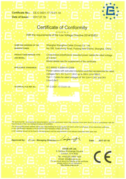
Kabel Shanghais Shenghua (Gruppe) Co., Ltd.
The earthing conductor is the least glamorous item in a cable schedule and the one that determines whether a fault trips a breaker or kills someone. Sizing it correctly, identifying it correctly and testing it correctly are three separate disciplines, and all three are frequently skipped on projects where the phase conductors received detailed attention. This guide explains what a protective earth conductor has to do, how its cross section is derived from the phase conductor under IEC 60364 practice, why green-yellow identification must run the full length, and how concentric conductors and separate earth cables differ in practice. It ends with six answers on sizing, testing, bonding and the mistakes that inspectors find most often.

A protective conductor, often written PE or CPC, provides a low impedance path for fault current so that protective devices operate quickly, and it holds exposed metalwork at a safe potential during the fault. Two different requirements follow from that, and they are often confused. The first is thermal: the conductor must survive the fault current for the time the protection takes to clear. The second is electrical: the total fault loop impedance must be low enough for the device to trip within the permitted time.
The classic sizing rule from IEC 60364 practice is simple to apply and easy to remember. Where the phase conductor is 16 mm2 or smaller, the protective conductor may be the same size. Where the phase conductor is between 16 and 35 mm2, the protective conductor may be 16 mm2. Where the phase conductor is larger than 35 mm2, the protective conductor may be half the phase conductor size. The rule assumes a copper protective conductor in the same cable as the phase conductor and a normal fault clearing time, and it should be checked against the adiabatic equation where fault levels are high or clearing times are long.
| Phase conductor S | Minimum protective conductor | Example |
|---|---|---|
| S 16 mm2 or less | S | 4 mm2 phase, 4 mm2 PE |
| 16 S 35 mm2 | 16 mm2 | 25 mm2 phase, 16 mm2 PE |
| S over 35 mm2 | S/2 | 120 mm2 phase, 60 mm2 PE |
| Aluminium PE | Larger, conductivity adjusted | Confirm by calculation |
Two construction options exist in cable form. The first is a cable with a dedicated green-yellow core, which is the normal arrangement for building wire and small multicore cable. The second is a concentric conductor, as in NYCY or CYKY, where a copper layer or a set of copper wires surrounds the cores and serves as both protective conductor and screen. Concentric conductors are convenient on buried distribution because they provide an earth path without a separate core, but their resistance and their behaviour at joints must be checked as carefully as any other conductor.
Earthing errors do not usually cause equipment to stop working. They cause equipment to keep working while the protection is ineffective, which is a far worse outcome.
1. High fault loop impedance. An undersized or poorly connected protective conductor raises the loop impedance, so the fault current is lower than the device expects. A breaker that should trip in 0.4 seconds may take several seconds or not trip at all, and during that time the exposed metalwork is at a dangerous potential. This is the failure mode that produces fatal accidents on apparently normal installations.
2. Borrowed neutral and shared earth. A neutral used as an earth in one part of an installation, or an earth shared between circuits with different isolation points, creates a situation where metalwork can become live when one circuit is isolated. It also defeats residual current protection, because the current path bypasses the sensor.
3. Poor identification. A protective conductor identified only by sleeving the ends, or a green-yellow core reused as a phase, causes exactly the confusion the colour code exists to prevent. During maintenance, the electrician trusts the colour and is exposed to a live conductor.
4. Corrosion at the electrode and bonds. An earthing system that is correct at commissioning can degrade at the connection rather than in the cable. Aluminium to copper joints, untinned connections in damp pits and loose clamps all raise resistance over time, and the change is invisible unless it is measured.
5. Concentric conductor joints. A concentric conductor must be carried through joints with the same care as a core. A joint that restores the phases and leaves the concentric layer poorly connected creates a cable with a good electrical performance and no earth path, which is the worst combination.
Size from the phase conductor using the table above, then verify with the adiabatic check for the actual fault level. Where the protective conductor is not in the same cable as the phase conductors, or where it is a separate earth cable, the sizing rules change and the calculation must be repeated. For aluminium conductors, adjust for conductivity rather than applying the copper rule directly.
Decide the construction early. A multicore cable with a dedicated green-yellow core is simplest for building work. For buried distribution, a concentric conductor cable such as NYCY or CYKY gives a robust combined earth and screen. Where no earth core is provided, as with NYY-O, a separate protective conductor must be run and its route, protection and identification specified at the same time as the phase cable.
Then control the connections. Every joint and termination must carry the protective conductor through with a connection of at least the same cross section and quality as the phase joints. Use tinned or copper connectors in damp locations, torque them to specification, and protect them against corrosion. For earthing electrodes, measure the resistance after installation and record it, then re-measure at defined intervals, because an electrode that reads two ohms at commissioning can read twenty after a dry season if the soil has changed.
Verify with the right tests. Protective conductor continuity to every exposed conductive part, fault loop impedance at the far end of each circuit, and earth electrode resistance are the three measurements that matter. Continuity alone does not prove that the loop impedance is adequate, and a low loop impedance at the board does not prove it at the extremity of a long circuit. Record the values per circuit, because the far end is where the weakest value will appear.
Finally, document the earthing arrangement: the system type, the electrode location, the bonding points, the conductor sizes and the test results. That record is what allows the next engineer to extend the installation safely, and it is the first thing an inspector will ask for on a fault investigation.
| Element | Requirement | Verification |
|---|---|---|
| PE in multicore cable | Green-yellow full length | Visual, full length check |
| Concentric conductor | Carried through joints | Resistance measurement at joints |
| Separate earth cable | Sized, protected, identified | Continuity and loop impedance |
| Electrode | Resistance as designed | Measured and recorded |
| Bonding | All extraneous metalwork | Continuity to each point |
Cable options that support these arrangements include the NYY and NYCY fire resistant cable with concentric conductor, the CYKY 5x10mm2 underground distribution cable, and the NYY 4x25mm2 PVC insulated cable where a separate earth is run. Building circuits typically use the BVR 1x4mm2 flexible PVC building wire in green-yellow for the protective conductor, and panel work uses the VGV 3x2.5mm2 rigid PVC wire 1 kV. Where earthing is combined with a metallic screen, the N2XRY 4x35mm2 wire armoured cable provides an armour that can serve as a bonding path where the installation design permits it.
During a fault the protective conductor carries a large current for a short time, and its temperature rises along with the phase conductor. The adiabatic equation relates the permitted temperature rise to the conductor material, the cross section and the fault duration, and it is the check that catches installations where the table rule alone is insufficient. A long clearing time, a high fault level or a protective conductor in a poor thermal environment can all make the table value inadequate. Where the protective conductor is a separate cable laid in a hot duct, or a metallic screen with limited cross section, the check becomes essential rather than optional.
The same fault current flows through the joints as through the conductor, which is why joint quality matters as much as cable size. A crimp with the wrong die, a connector of a different metal or a clamp tightened by feel will add resistance at exactly the moment the current is highest. Thermal imaging after a test, or simply re-torquing to specification and recording it, prevents the loose earth connection that quietly turns a compliant design into a dangerous one.
The protective arrangement differs between TN, TT and IT systems, and the cable specification follows. In a TN-S system the protective conductor runs separately from the neutral for the whole installation, so a cable with a dedicated earth core is the natural choice. In a TN-C-S arrangement the combined PEN conductor splits at the origin, and the specification must define exactly where that split occurs so that no combined conductor continues into final circuits. In a TT system the fault loop returns through the earth electrode, so electrode resistance and residual current protection carry the safety function, and the protective conductor in the cable is a bonding path rather than the fault return.
None of this changes the colour requirement, but it changes the sizing and the test values. Buyers working across markets should state the earthing system in the enquiry, because a cable and a design that satisfies one system may not satisfy another, and the difference is not visible in the cable designation.
Finally, treat the protective conductor as a deliverable with its own paperwork. The cable schedule should show the PE size for each circuit, the construction that carries it, and the test result that proves it. When those three items are visible in the project file, the earthing stops being an assumption and becomes a verifiable part of the design, which is precisely what an inspector, an insurer or a future maintenance team needs in order to trust the installation.
Under IEC 60364 practice, S equals the phase conductor up to 16 mm2, is 16 mm2 for phase conductors from 16 to 35 mm2, and is half the phase conductor above 35 mm2, subject to an adiabatic check.
No. A combined neutral and earth is only permitted in specific distribution arrangements such as PEN in TN-C systems, and never in final circuits of an installation using separate protective conductors.
Yes. Sleeving the ends of a core of another colour is not acceptable identification, because the sleeve can move and the underlying colour contradicts it.
It can be, provided its cross section and the joints are correctly designed. The advantage is a combined earth and screen; the risk is a joint that fails to carry the concentric layer.
Protective conductor continuity, fault loop impedance at the extremity of each circuit, and earth electrode resistance. Continuity alone is not sufficient.
Sometimes, where the installation standard permits and the armour cross section and conductance are adequate. It must be verified by calculation and by resistance measurement.
Earthing is a chain, and its strength is set by the weakest element: the conductor size, the joint, the identification and the electrode. Size from the phase conductor, apply the adiabatic check, run green-yellow for the full length, carry concentric conductors through every joint, and test at the far end rather than at the board. Recorded results are what turn an installation into a verifiable one. Shanghai Shenghua Cable Group manufactures PVC and XLPE cable with green-yellow earth cores and with concentric conductors in NYCY and CYKY constructions, from building wire to 33 kV distribution cable. Send your earthing design and fault levels through our contact page and our engineers will confirm the conductor sizes, the construction and the test protocol.